


 |
OEM Customized Cnc End Mill Cutter Aluminum Milling 2 Inch Ball Nose End Mill
Product Details:
| Place of Origin: | China |
| Brand Name: | BWIN |
| Model Number: | R4*16*d8*100L-2F |
Payment & Shipping Terms:
| Minimum Order Quantity: | 20pcs |
|---|---|
| Price: | Negotiable |
| Packaging Details: | Plastic box |
| Delivery Time: | 7 work days |
| Payment Terms: | T/T, Western Union |
| Supply Ability: | 1-10000pcs 7days |
|
Detail Information |
|||
| Product Name: | HRC45 2F Aluminum Cnc Carbide End Mill | Model: | φ4*10*d4*50L-4F End Mill |
|---|---|---|---|
| Material: | Tungsten Square Milling Cutter | Workpiece: | Alloy Steel |
| Usage: | Milling | Coating: | AlTiN |
| HRC: | HRC45 | Feature: | High Hardness |
| Application: | CNC Machine | Package: | 1pcs/Box |
| Highlight: | Aluminum Milling Cnc End Mill Cutter,Aluminum Milling 2 Inch Ball End Mill,Customized Cnc End Mill Cutter |
||
Product Description
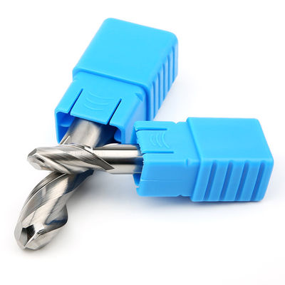
Carbide End Mill R4 Ball Nose HRC45 2F Tungsten Steel Aluminum Milling Cutter 45 Degree
Characteristic:
- Compared with the end milling cutter, the ball cutter does not have a sharp blade at the bottom of the end milling cutter, but a blade with an R angle, so the blade of the ball cutter is stronger and not easy to break
- The contact area between the ball cutter and the workpiece is the blade with an R angle, so a larger value can be used for tool spacing during finishing
- Ball cutters are most commonly used to mill 3D molds in mold processing, but they are not suitable for milling flat areas. Because of the small contact area with the workpiece, the tool spacing cannot be increased
Description:
- A more stable processing state can be obtained: when using the ball nose carbide end mill for processing, the cut in angle changes continuously without sudden change, so the change of cutting force is a continuous change process, which can ensure a more stable cutting state and a higher surface finish.
- Ball head carbide end mill is used for semi finishing and finishing of curved surfaces: the spindle motor we use has a poor ability to resist axial force, so it is generally not allowed to use ball head cutter for rough machining, while in semi finishing, it is very good to use ball head cutter. After semi finishing with a ball end cutter, there is less machining residue, which is more conducive to the following finishing. The path spacing of semi finishing is generally the two sides of the finishing spacing. If the method of parallel intercept is used, it is 90 degrees from the tool path direction of finishing.
- Reduced the actual cutting radius: just like the use of a bull nose knife, the use of a ball nose carbide end mill reduces the actual cutting diameter, reduces the cutting linear speed, reduces the cutting power and cutting torque during cutting, and is more conducive to the processing of the spindle motor in a better state.
Milling parameters:
| HRC45 Carbide End Mill |
Tool length | fz&v | |||||
| Short |
1 |
||||||
| Long1 | 0.9 | ||||||
| Overlength | 0.8 | ||||||
| Speciality | 0.6 | ||||||
| Type | Material |
Strength N/mm²
Hardness HRC |
Cooling | ||||
| Air |
Dry cutting |
Lubricating fluid | |||||
| P | PI |
P1.1 |
Non alloy structural steel, free cutting structural steel, carburized steel and quenched and tempered steel | <700 | √ | √ | √ |
| P1.2 | quenched and tempered steel | <1200 | √ | √ | √ | ||
| P2 | P2.1 | Alloyed nitrided steel, carburized steel and quenched and tempered steel | <900 | √ | √ | √ | |
| P2.2 | Tool steel, bearing steel, spring steel and high-speed steel | <1400 | √ | √ | |||
| P3 | P3.1 | Tool steel, bearing steel, spring steel and high-speed steel | <900 | √ | √ | √ | |
| P3.2 | Tool steel, bearing steel, spring steel and high-speed steel | <1500 | √ | √ | |||
| Sloting | ||||||||||||
| Vc (m/min) |
fz(mm/Tooth) | |||||||||||
| Diameter | ||||||||||||
| 2 | 4 | 6 | 8 | 10 | 12 | 16 | 20 | |||||
| 112 | 0.01 | 0.018 | 0.026 | 0.034 | 0.041 | 0.048 | 0.06 | 0.069 | ||||
| 92 | 0.01 | 0.017 | 0.025 | 0.032 | 0.038 | 0.045 | 0.056 | 0.065 | ||||
| 100 | 0.01 | 0.018 | 0.026 | 0.034 | 0.041 | 0.048 | 0.06 | 0.069 | ||||
| 72 | 0.009 | 0.015 | 0.022 | 0.028 | 0.034 | 0.04 | 0.05 | 0.058 | ||||
| 64 | 0.01 | 0.018 | 0.025 | 0.032 | 0.039 | 0.045 | 0.057 | 0.066 | ||||
| 56 | 0.009 | 0.016 | 0.023 | 0.029 | 0.036 | 0.041 | 0.052 | 0.06 | ||||
| Roughing | ||||||||||||
| Vc (m/min) |
fz(mm/Tooth) | |||||||||||
| Diameter | ||||||||||||
| 2 | 4 | 6 | 8 | 10 | 12 | 16 | 20 | |||||
| 228 | 0.018 | 0.031 | 0.045 | 0.057 | 0.070 | 0.081 | 0.101 | 0.118 | ||||
| 208 | 0.017 | 0.029 | 0.042 | 0.054 | 0.065 | 0.071 | 0.095 | 0.11 | ||||
| 184 | 0.018 | 0.031 | 0.045 | 0.057 | 0.070 | 0.081 | 0.101 | 0.118 | ||||
| 144 | 0.015 | 0.026 | 0.037 | 0.048 | 0.058 | 0.068 | 0.085 | 0.098 | ||||
| 132 | 0.017 | 0.03 | 0.042 | 0.054 | 0.066 | 0.077 | 0.096 | 0.112 | ||||
| 112 | 0.015 | 0.027 | 0.039 | 0.05 | 0.060 | 0.07 | 0.088 | 0.102 | ||||
| Finish | |||||||||||
| Vc m/min |
fz(mm/Tooth) | ||||||||||
| Diameter | |||||||||||
| 2 | 4 | 6 | 8 | 10 | 12 | 14 | 16 | 18 | 20 | ||
| 332 | 0.028 | 0.05 | 0.07 | 0.091 | 0.11 | 0.128 | 0.144 | 0.16 | 0.173 | 0.186 | |
| 272 | 0.026 | 0.046 | 0.066 | 0.085 | 0.103 | 0.12 | 0.135 | 0.15 | 0.162 | 0.173 | |
| 304 | 0.028 | 0.05 | 0.07 | 0.091 | 0.11 | 0.128 | 0.144 | 0.16 | 0.173 | 0.186 | |
| 212 | 0.023 | 0.041 | 0.059 | 0.076 | 0.092 | 0.107 | 0.121 | 0.134 | 0.145 | 0.155 | |
| 196 | 0.027 | 0.047 | 0.067 | 0.086 | 0.104 | 0.122 | 0.137 | 0.152 | 0.165 | 0.177 | |
| 168 | 0.024 | 0.043 | 0.061 | 0.079 | 0.095 | 0.111 | 0.125 | 0.139 | 0.150 | 0.161 | |
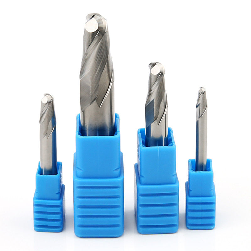
- If the following carbide end mill cannot meet your requirements, we support OEM customized production. The diameter of 0.2mm to 25mm, the total length of 50mm to 200mm, 4F, 5F, 6F, 8F and logo can be customized, including inch size end milling cutter. Please contact us to select or customize non-standard carbide end mill according to your needs.
| Specification | Flute Dia(φ) | Flute Length (C) | Shank Dia(D) | Overall Length(L) |
| R0.5*2*d4*50L | 0.5 | 2 | 4 | 50 |
| R0.75*3*d4*50L | 0.75 | 3 | 4 | 50 |
| R1*4*d4*50L | 1 | 4 | 4 | 50 |
| R1.25*5*d4*50L | 1.25 | 5 | 4 | 50 |
| R1.5*6*d4*50L | 1.5 | 6 | 4 | 50 |
| R1.75*7*d4*50L | 1.75 | 7 | 4 | 50 |
| R2*8*d4*50L | 2 | 8 | 4 | 50 |
| R2.5*10*d5*50L | 2.5 | 10 | 5 | 50 |
| R3*12*d6*50L | 3 | 12 | 6 | 50 |
| R4*16*d8*60L | 4 | 16 | 8 | 60 |
| R5*20*d10*75L | 5 | 20 | 10 | 75 |
| R6*24*d12*100L | 6 | 24 | 12 | 100 |
| R7*28*d14*150L | 7 | 28 | 14 | 150 |
| R8*32*d16*100L | 8 | 32 | 16 | 100 |
| R9*36*d18*100L | 9 | 36 | 18 | 100 |
| R10*40*d20*100L | 10 | 40 | 20 | 100 |
- Minimize the use of tool tips to process workpieces: at the position of the ball head tool tip, the processing linear speed is 0 during actual processing, that is, the tool is not actually cutting, but grinding. In actual processing, the coolant can not be added to the cutting area at all, which further leads to greater cutting heat ratio and reduced tool life.
- For straight wall processing, use contour contour processing method: try to reduce the phenomenon of ball end cutter processing downward along the straight wall. Relatively speaking, it is a very good method to process upward along the straight wall, but it is difficult to separate them in actual processing. Let's compare the differences between the two.
- Machining straight wall with contour can reduce downward machining. If you can use "cutting from bottom to top", this phenomenon can be avoided. When using "cutting from bottom to top", first consider whether the cutting capacity of the cutter is too large. If there are relatively large residues left at the root of the curved surface after machining above, the cutting capacity of the cutter may be too large. This will not protect the tool but destroy it.
- The ball end milling cutter shall pay attention to the processing of deep grooves: when processing deep grooves, the cutter may sink. Because the chip holding groove of the ball end milling cutter is relatively small, it is easy to break the cutter when processing sticky materials (such as red copper) and the feed speed is fast. Therefore, pay attention to chip removal when using ball end cutter for machining.
Applications:
Pre-hardened Steel, stainless steel, Die steel, steel plate, Heat-resistant steel,pipe, copper and aluminum, cast iron, Nonferrous Metal, Wood, Plastic,FRP and sO on. General-purpose operation slotting, rilling, profiling.
![]()
Q1. The tool breaks when cutting in or pulling out the workpiece
The feed rate and cutting depth can be reduced, and the cutting edge length can be shortened to the minimum of the necessary length.
Q2. Tool breaks during normal machining
Reduce the feed rate and cutting depth.
The tool shall be passivated.
Replace the clamp or spring collet.
The tool with high cutting edge number changes the tool with low cutting edge number to improve chip removal and prevent chip blockage.
Replace dry milling with wet milling (using cutting fluid), and use it with vortex tube gun to reduce tool temperature and avoid tool overheating.
If the wet milling fluid supply direction is changed from the front to the oblique rear or transverse top, the coolant flow should be sufficient.
Q3. The tool breaks when the feed direction changes
(1) Use arc interpolation (NC machine tool), or temporarily stop (temporarily) feeding.
(2) Reduce (decrease) the feed before and after the direction change.
(3) Replace the clamp or spring collet.
Q4. Problem: Part of the blade tip breaks
Chamfer the corners with manual grinding.
Change down milling to up milling.